Build the camera itself: Difference between revisions
mNo edit summary |
mNo edit summary |
||
| Line 2: | Line 2: | ||
<table><tr><td> | <table><tr><td> | ||
== | == Prepare the lens == | ||
There are two types of lens holders - a holder with a single filter and a holder with an electronic filter drawer. | There are two types of lens holders - a holder with a single filter and a holder with an electronic filter drawer. | ||
| Line 41: | Line 41: | ||
<table><tr><td> | <table><tr><td> | ||
== | == Attach the lens to the camera == | ||
[[File:lensattaching.jpg|thumb|right|Attaching the Lens]] | [[File:lensattaching.jpg|thumb|right|Attaching the Lens]] | ||
| Line 53: | Line 53: | ||
<table><tr><td> | <table><tr><td> | ||
== | == Prepare the camera housing == | ||
[[File:glands.jpg|thumb|right|Glands in Place]] | [[File:glands.jpg|thumb|right|Glands in Place]] | ||
a. Fit the small cable gland to the housing. | a. Fit the small cable gland to the housing. | ||
| Line 67: | Line 67: | ||
<table><tr><td> | <table><tr><td> | ||
== | == Attach the camera == | ||
[[File:camerafitted.jpg|thumb|right|Camera In Mount]] | [[File:camerafitted.jpg|thumb|right|Camera In Mount]] | ||
| Line 86: | Line 86: | ||
<table><tr><td> | <table><tr><td> | ||
== | == Install the camera in the housing == | ||
[[File:camerainhousing.jpg|thumb|right|Camera In Housing]] | [[File:camerainhousing.jpg|thumb|right|Camera In Housing]] | ||
| Line 105: | Line 105: | ||
<table><tr><td> | <table><tr><td> | ||
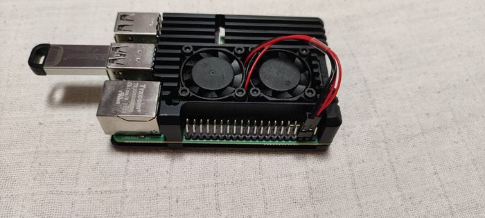
== | == Install cooling fans in hoousing of the Raspberry Pi 4 == | ||
In this step, you install two fans into the case. | |||
a. Remove the foil from the pads. | |||
b. Hold the fans in place, as sown in the figure, then screw the case together. | |||
c. Plug in the fan wires, as shown in the figure. | |||
[[File:Raspi4_in_case_small.jpg|700px]] | [[File:Raspi4_in_case_small.jpg|700px]] | ||
| Line 113: | Line 119: | ||
</td></tr></table> | </td></tr></table> | ||
Now, the camera is ready. | |||
Next, you flash the RMS Linux image onto the SD card or USB key. [https://globalmeteornetwork.org/wiki/index.php?title=Build_%26_Install_%26_Setup_your_camera_-_The_complete_how-to Back to the signpost page.] | |||
Latest revision as of 07:54, 28 August 2025
Most people think this section is the most fun. Here, you put all the pieces together. If you find something that is not particularly clear, let us know in the forums.
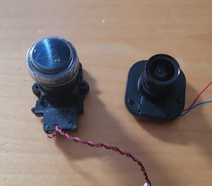
Prepare the lensThere are two types of lens holders - a holder with a single filter and a holder with an electronic filter drawer. a. Remove the protective covers from the sensor and the lens.
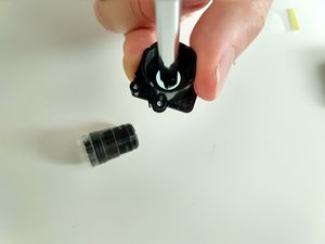
The cameras come with an IR Block filter in the lens holder, but we do not use this filter. b. If you have a lens with a single filter like the one shown in the first image, unscrew the lens from the holder. c. With a screwdriver, carefully push the filter out of the lens holder, as shown in the image on the right.
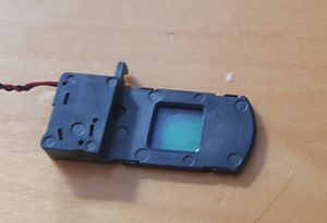
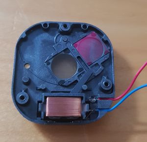
d. If your holder is the type with a rectangular sliding drawer, remove the screw on the end and remove the drawer. Then remove the while filter glass entirely. e. If your holder has a single drawer, remove the three small screws on the top and take off the cover. f. Remove the clear filter.
g. Reassemble the filter holder, but do not connect the power cable to the camera. h. Turn the lens holder over to see two plastic nubbins on the underside of the lens holder.
i. Screw the lens back into the lens holder. |
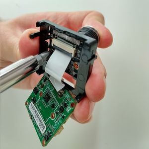
Attach the lens to the cameraa. If you have an IMX291, carefully unclip the circuit board from the plastic holder, but do not detach the ribbon cable. (IMX307 is a single board) b. Use the supplied screws to attach the lens to the sensor.
c. Replace the circuit board in the plastic holder. |
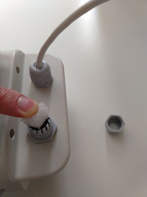
Prepare the camera housinga. Fit the small cable gland to the housing. b. Pass the loose ends of the camera PoE cable up through the housing, but do not tighten the cable. c. Slip the cap over the cable, then tighten the cable. b. Fit the large cable gland in the other opening, and push a piece of plastic packing foam into it.
|
Attach the cameraAt this time, you have the option to test the focus before you install the camera in the housing. If you do, skip this section for now and come back later.
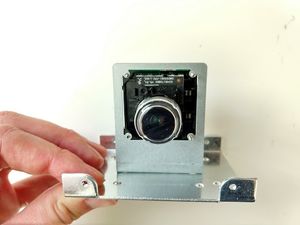
a. Connect the metal camera holder to the metal plate using (1) 6mm M3 screw.
b. Pass the lens through the square hole from the back of the metal holder, then use (3) 12 mm M2 screws to connect the camera board to the holder.
To be sure you have the correct orientation, refer to the section titled, Testing and focus. c. Remove the plastic cap from the lens.
|
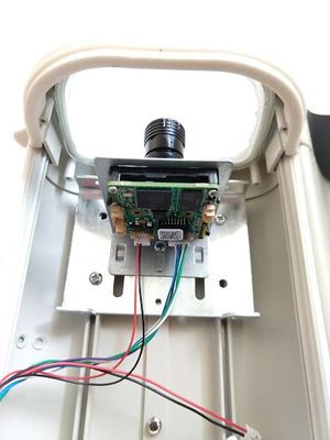
Install the camera in the housinga. Remove the plastic plate from inside the housing and discard it. b. Position the camera on its metal plate inside the housing, as close to the front glass as you can but do not come in contact with the glass.
c. Orient the camera so you can see it from the rear, then attach the largest connector to the right-hand socket.
d. Attach the power connector to the left-hand socket. This connector has several pins, but only the pins on the red and black wires are connected. e. The third connector (also with red and black wires) is used with a powered lens, which is not part of this installation. Tape the connector out of the way. f. After you secure the camera in position, tighten the cable glands. |
Now, the camera is ready.
Next, you flash the RMS Linux image onto the SD card or USB key. Back to the signpost page.
