|
|
| Line 41: |
Line 41: |
| <table><tr><td> | | <table><tr><td> |
|
| |
|
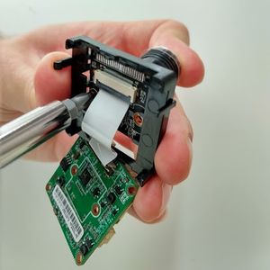
| == Attaching the Lens to the Camera == | | == 2. Attach the lens to the camera == |
| [[File:lensattaching.jpg|thumb|right|Attaching the Lens]] | | [[File:lensattaching.jpg|thumb|right|Attaching the Lens]] |
|
| |
|
| * Carefully unclip the circuit board from the plastic holder but do not detach the ribbon cable. (Only for IMX291, IMX307 is just a single board)
| | a. If you have an IMX291, carefully unclip the circuit board from the plastic holder, but do not detach the ribbon cable. (IMX307 is a single board) |
|
| |
|
| * Using the supplied screws, attach the lens to the sensor. '''Please be careful when installing the lens onto an IMX307 module, transistors and capacitors are very close to the area where a lens will be placed.'''
| | b. Use the supplied screws to attach the lens to the sensor. |
| | : '''IMPORTANT:''' Transistors and capacitors are very close to the area where a lens will be placed. When you install the lens onto an IMX307 module, be very careful. |
|
| |
|
| * Replace the circuit board in the plastic holder.
| | c. Replace the circuit board in the plastic holder. |
|
| |
|
| </td></tr></table> | | </td></tr></table> |
Revision as of 23:00, 27 August 2025
Most people think this section is the most fun. Here, you put all the pieces together. If you find something that is not particularly clear, let us know in the forums.
1. Prepare the lens
There are two types of lens holders - a holder with a single filter and a holder with an electronic filter drawer.
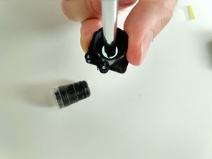 single filter: punch out the filter a. Remove the protective covers from the sensor and the lens.
- IMPORTANT: Be careful not to touch the sensor after you remove the cover.
The cameras come with an IR Block filter in the lens holder, but we do not use this filter.
b. If you have a lens with a single filter like the one shown in the first image, unscrew the lens from the holder.
c. With a screwdriver, carefully push the filter out of the lens holder, as shown in the image on the right.
- NOTE: If you push from the front, the filter may come out intact. If it shatters, make sure to remove all the shards.
- Some lenses have an electronic day/night filter drawer and a small cable that plugs into the camera board. Two types of filter holders are shown here.
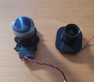 Two sorts of lens holder with day/night filters - WARNING: DO NOT try to directly punch out the filter. This action may jam the mechanism or leave shards of glass inside.
d. If your holder is the type with a rectangular sliding drawer, remove the screw on the end and remove the drawer.
Then remove the while filter glass entirely.
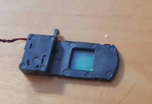 Sliding type: Remove the filter entirely e. If your holder has a single drawer, remove the three small screws on the top and take off the cover.
f. Remove the clear filter.
- You can leave the reddish daylight filter.
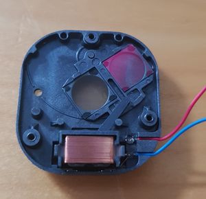 Rotating type: Remove just the clear filter g. Reassemble the filter holder, but do not connect the power cable to the camera.
h. Turn the lens holder over to see two plastic nubbins on the underside of the lens holder.
- Use wire cutters to snip off the nubbins.
- NOTE: You must make the base completely flat.
i. Screw the lens back into the lens holder.
|
2. Attach the lens to the camera
a. If you have an IMX291, carefully unclip the circuit board from the plastic holder, but do not detach the ribbon cable. (IMX307 is a single board)
b. Use the supplied screws to attach the lens to the sensor.
- IMPORTANT: Transistors and capacitors are very close to the area where a lens will be placed. When you install the lens onto an IMX307 module, be very careful.
c. Replace the circuit board in the plastic holder.
|
Preparing the Camera Housing
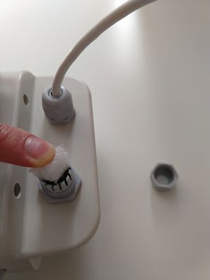
- Fit the small cable gland to the housing and pass the loose ends of the Camera PoE cable up through, but don't tighten it up yet. Remember to slip the cap over the cable first!
- Fit the large cable gland in the other opening, and push a piece of plastic packing foam into it. Don't seal it up completely though this is to keep insects from getting in, but allow moisture out.
- We do not recommend that you put the whole cable inside the housing, as the LEDs on it will create light pollution inside the housing.
|
Attaching the Camera
Note: I recommend installing the camera in the housing at this point so that you do not have to detach the cables or risk knocking focus later on. However, you can proceed to test focus etc before installing the camera in the housing if you wish. If you prefer to do that, skip this section for now and come back later. Otherwise:
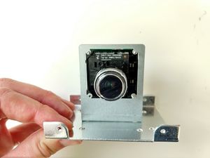
- Connect the metal camera holder to the metal plate using one 6mm M3 screw. Note the orientation of the plate as shown in the photo.
- Using three 12 mm M2 screws, connect the camera board to the metal holder, passing the lens through the square hole from the back.
- Note that on some camera models, the writing on the camera board or image of a stick man must be UPSIDE DOWN to get the correct orientation of the camera. In this orientation, the sockets for power and networking will be at the bottom of the rear of the camera board. To be sure you have it the right way up, see advice in the section on Testing and Focusing.
- Finally, remove the plastic cap on the lens.
See image for the proper camera board orientation, so the video is not sideways or upside down.
|
Installing the Camera in the Housing
- Remove the plastic plate from inside the housing and discard it.
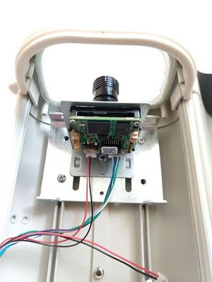
- Fit the camera on its metal plate into the housing, as close to the front glass as you can get it without actually touching. A few millimetres away should be good.
- Looking at the camera from the rear, attach the largest connector (often with blue/green wires) to the right hand socket.
- Attach the power connector to the left hand socket. This connector has several pins but only two are connected (red/black).
- The third connector (two pins, red/black) is for a powered lens and is not used so tape it back out of the way.
- Once you've secured the camera in position, you can tighten up the cable glands.
|
Installing the cooling housing to the Raspberry Pi 4
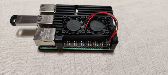
Install 2 fans into the case, remove the foils from the pads, put the in place, and screw the case together. Then plug in the wires of the fans as per the below picture.
|
Perfect! Now you have the camera part ready. Let’s continue with flashing the RMS Linux image onto an SD card or a USB key. Back to the signpost page.


